
Threaded Rivets create reusable internal threads in sheet materials that cannot accept a conventional nut. They are useful in enclosures, vehicle panels, equipment housings, and other assemblies with limited rear access. Installation may look simple. The result still depends on careful preparation.
Grand View Research’s Industrial Fasteners Market Report valued the global market at approximately USD 90.4 billion in 2023 and forecast continued growth through 2030. That figure reflects the wide use of fastening systems, but it does not mean every insert suits every panel. NASA’s Fastener Design Manual, NASA RP-1228, likewise treats fastener choice as an engineering decision shaped by joint design and operating loads. Check the rivet’s material, grip range, thread size, and manufacturer instructions before drilling.
This guide explains how to install Threaded Rivets with a hand tool or powered setting tool. You will learn how to select the correct hole size, keep the insert square, and recognize a properly set rivet. A tilted insert can damage threads or leave the joint loose. Small details matter. Tool settings and panel thickness vary, so a test installation on scrap material is a sensible check—not an unnecessary extra step.
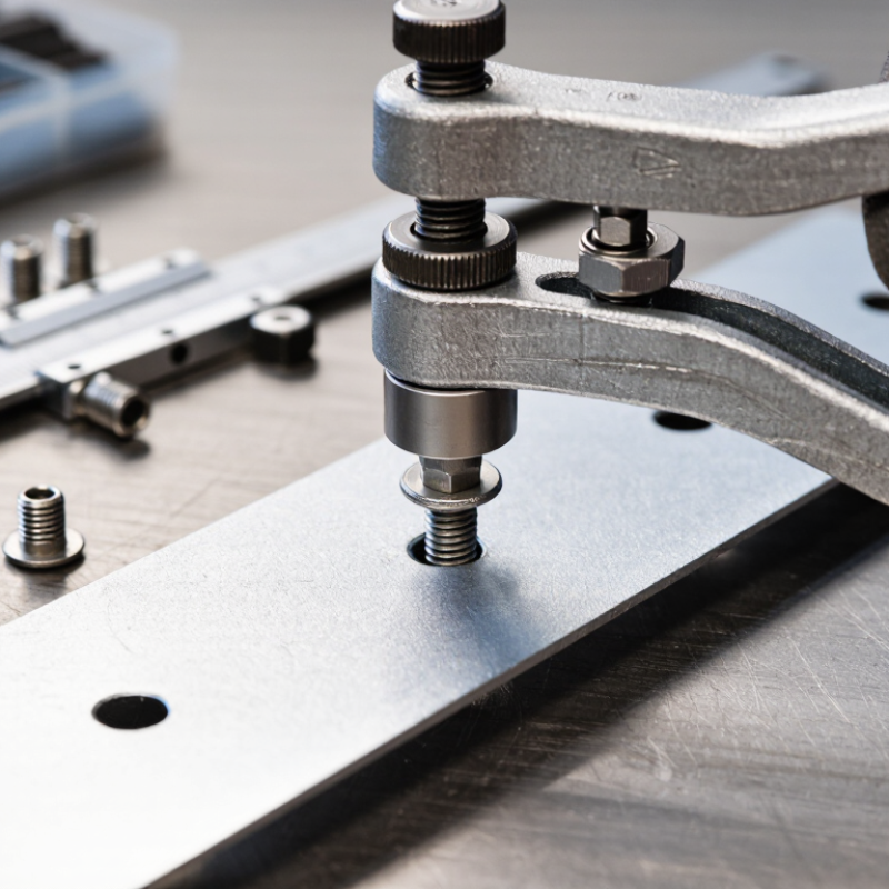
Identify each threaded rivet by its body shape, material, thread size, and stated grip range. A smooth body differs from a knurled one; knurls help resist spinning in softer sheet. Check whether the rivet is open-ended or closed-ended, and note its flange shape. These details affect access and how the part sits against the panel. Measure the full panel stack, including paint or coatings, instead of guessing from one sheet. Grip range matters. A rivet that is too long may spin, while one that is too short may not clamp securely. Confirm that its internal thread matches the fastener you plan to use.
Choose an installation tool with a nosepiece and threaded mandrel that match the rivet’s thread. A mismatched mandrel can damage the threads or prevent proper setting. For occasional repairs, a hand setter may be sufficient if it supports the rivet size and material. Repeated installations may call for a powered tool with adjustable pull or stroke settings. Avoid applying more force than the rivet requires; over-setting can distort the flange or panel. Before working on the finished part, test the setup on a scrap piece of the same thickness. Check that the rivet sits flat and does not rotate when you turn in a bolt. Coatings are easy to overlook. I would check that measurement twice.

Measure the workpiece thickness before choosing a threaded rivet. The insert’s grip range must cover the material, or the back side may not form correctly. Check the installation chart for the exact hole diameter. Industrial rivet-nut charts commonly list 9.0 mm for some M6 inserts, but this is not a universal specification. NASA’s Fastener Design Manual (NASA RP-1228) discusses the importance of controlling fastener-hole fit; follow the insert maker’s stated dimensions for your specific part.
Mark the hole center, then clamp the panel securely. Drill perpendicular to the surface, using a sharp bit and steady pressure. Remove burrs from both sides, but do not enlarge the opening while deburring. A caliper helps verify the diameter; also check that the hole is round and free of chips. A hole that looks close can still be oversized. I have found that rechecking the measurement is faster than correcting a loose insert later.
Tips: Test-drill scrap material of the same type and thickness. Confirm the finished hole with the specified gauge or caliper before installation. Keep the insert square to the panel. Avoid assuming that one drill size fits every M6 rivet nut; styles and tolerances differ.
Choose a mandrel and nosepiece that match the threaded rivet’s internal thread size. Check the tool instructions before fitting parts, since adjustment methods can differ. A mismatched nosepiece may let the rivet wobble or sit crooked. Keep the rivet and tool clean; grit can make the threads feel rough.
Hold the tool steady and turn the rivet onto the mandrel by hand. It should engage smoothly. Go gently. If it catches after a turn or two, stop and back it off rather than forcing it; crossed threads are easy to miss at first. Continue until the rivet’s flange rests squarely against the nosepiece, with no visible gap. The flange should not tilt, and the rivet should not spin loosely. A small amount of resistance near the end can be normal, but binding is not. Check that the mandrel extends into the rivet far enough to engage its threads securely. Some tools need a setting adjustment before use, so confirm the tool’s directions rather than guessing. It can feel fiddly, especially with small rivets. If the fit still feels uneven, remove the rivet and inspect both sets of threads under good light. A quick visual check can prevent a poor installation.
Set the rivet in the workpiece
Clean the hole and check its diameter against the insert’s installation specification. A hole that is too large can let the rivet nut spin; one that is too small may damage its body during insertion. Keep the tool square to the sheet. Even a slight angle can leave the flange uneven, especially on thin panels. NASA’s Fastener Design Manual (RP-1228) compiles fastener strength and joint-design data, underscoring why the workpiece and fastener should be treated as one assembly—not judged by appearance alone.
Tip: Use a grip range suited to the workpiece thickness. Place the insert fully against the surface, then operate the setting tool with a controlled pull. Stop when the flange seats firmly; excessive setting force can deform the panel or strip the insert’s threads. Check the back of the joint for a consistent bulge, if accessible. It should not feel loose or rotate under light hand pressure. A quick thread check with the matching bolt helps, but it does not replace a load test when the application demands one.
I’ve seen rushed installations look neat from the front and still spin during fastening. That’s the part worth rechecking. If the insert turns, stop and inspect the hole size, grip range, and tool alignment before setting another one.
Before setting a threaded rivet, confirm its thread size and prepare the workpiece hole to the insert manufacturer's specification. The chart shows standard ISO metric thread nominal diameters; these values are not pilot-hole sizes.
After setting a threaded rivet, inspect the joint before applying a load. The flange should sit flat against the sheet, without a visible gap, tilt, or spun surface. Look for cracks, sharp burrs, and sheet distortion around the hole. These can signal a poor hole fit or an uneven installation. Small details matter.
Check the internal thread with the specified go/no-go gauge, not a random bolt. ISO 1502 defines gauging practice for metric threads, while ASME B1.2 covers unified inch threads. A go gauge should enter smoothly; a no-go gauge should not pass beyond the limit set for that thread. Record the thread size, gauge result, and any installation setting used. Then test the rivet’s rotation or pull-out resistance only against the application’s stated acceptance criteria. NASA’s Fastener Design Manual, Reference Publication 1228, discusses how joint behavior depends on fastener and installation conditions; appearance alone cannot confirm performance. I have seen a clean-looking flange conceal damaged threads. Recheck suspect parts with a fresh gauge, and replace any rivet that binds or spins.
| Installation Stage | Inspection Item | Method or Tool | Acceptance Check | Example Finding | Result |
|---|---|---|---|---|---|
| Before installation | Workpiece hole diameter | Calibrated pin gauge or suitable hole-measuring tool | Hole is within the specified range and free of burrs or damage. | Measured 9.1 mm; example drawing range: 9.0–9.2 mm | Pass |
| Before installation | Insert type and grip range | Check the part specification and total workpiece thickness | Insert thread size and grip range suit the application. | M6 insert selected; measured stack thickness falls within its specified grip range | Pass |
| Tool setup | Mandrel and nosepiece compatibility | Verify tool setup against the insert thread size and tool instructions | Correct mandrel and nosepiece are fitted; threads engage smoothly. | M6 setup fitted; insert threads onto mandrel by hand without binding | Pass |
| Setting | Tool alignment and seating | Visual inspection; check the insert face against the workpiece | Tool is held square to the workpiece; insert sits flat without visible rocking. | Insert face is flush and evenly seated | Pass |
| After setting | Set condition and workpiece surface | Visual inspection; compare the formed backside with the approved sample or specification | Insert is secure; no spinning, cracking, excessive deformation, or surface damage is present. | Insert does not rotate under a light manual check; no visible cracks | Pass |
| Thread inspection | Internal thread condition | Use the specified GO and NO-GO thread plug gauges | Gauge results meet the applicable thread standard and drawing requirements. | GO gauge engages as required; NO-GO gauge result meets the specified limit | Pass |
| Functional check | Fastener engagement | Thread in the specified mating screw by hand | Screw starts without cross-threading and turns smoothly through the required engagement. | M6 mating screw starts by hand and turns smoothly | Pass |
| Final inspection | Record and disposition | Record measurements, gauge results, and any nonconformance | All required checks are documented; nonconforming parts are identified and segregated. | Inspection recorded; no defects found in the example check | Pass |